
D. PHYSICAL MEDIA
The physical medium is the channel through which information is transmitted. It may be a cable (wired medium) or a wireless transmission (wireless medium). The choice of physical medium determines the maximum data rate, the range, susceptibility to interference and the installation cost.
|
Related media (guided) |
Unbound media (unguided) |
|
Twisted pair (UTP/STP/FTP) |
Wi-Fi (802.11a/b/g/n/ac/ax/be) |
|
Coaxial cable (10Base5, CATV) |
Laser / infrared (FSO) |
|
Optical fibre (MMF, SMF) |
Terrestrial and satellite microwaves |
|
Powerline communication (PLC) cable |
Mobile network (4G/5G) |
Physical media are evaluated on the basis of: available bandwidth, maximum distance before signal regeneration, resistance to electromagnetic interference (EMI/RFI), ease of installation and cost.
1. Optical fibre
Fibre optics represent one of the greatest technological advances in cabling. They transmit light generated by either a laser or an LED (Light-Emitting Diode, LED). They are unaffected by electromagnetic interference and offer complete protection against passive eavesdropping.
a) Fibre structure
An optical fibre consists of three concentric elements:
· The core: the central part of the fibre through which light rays travel. Made of glass (silica) or high-purity plastic.
· The optical cladding: surrounds the core with a material whose refractive index is lower than that of the core. This difference in refractive index confines the propagation of light rays through total internal reflection.
· The protective coating (coating/buffer): an outer layer that protects the optical fibre from physical damage (impact, moisture, crushing).
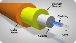
Fig. 12 — Structure of an optical fibre (core, cladding, coating)
An optical cable can transmit up to several hundred Gbps over distances of several kilometres — something no copper cable can achieve. Today, it is the standard solution for long distances and high data rates. Optical fibres range from 2 to 864 strands in a single cable (one strand per transmission direction, by convention).
ℹ Benefits of fibre optics
Very high data rates (from 1 Gbps to several Tbps per fibre with DWDM), complete resistance to electromagnetic interference, immunity to eavesdropping (tapping into a fibre physically cuts the connection), lightweight and compact, low attenuation over long distances. Minimum bend radius to be observed during installation (~ 10× the cable diameter).
b) Types of fibre
Multimode fibre (MMF): light rays follow multiple paths (modes) within the core, which causes modal dispersion that limits the transmission distance and data rate. Used for short distances (LAN, data centres). Transmitter: LED (850 nm) or VCSEL laser (850 nm). Standard dimensions: core 50 µm / cladding 125 µm (or 62.5/125 µm). Performance: from 1 Gbps/km (OM1) to 100 Gbps/100 m (OM5). A distinction is made between step-index fibres and gradient-index fibres (sinusoidal wave, better performance).
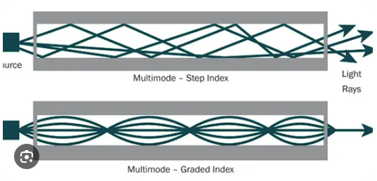
Fig. 13 — Propagation in a multimode fibre (index gradient and index jump)
Single-mode fibre (SMF): the light rays follow a single path (fundamental mode) within a very narrow core (5 to 10 µm / 125 µm cladding). The transmitter is a laser (1,310 nm or 1,550 nm) providing a very precise signal. Performance: > 100 Gbps/km, usable over tens to hundreds of kilometres. Chromatic dispersion (different wavelengths propagate at slightly different speeds) is the main limiting factor, corrected by dispersion compensators or DSF (Dispersion Shifted Fibre) fibres.
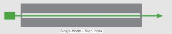
Fig. 14 — Propagation in a single-mode fiber (single mode, low dispersion)
|
Feature |
Multimode (MMF) |
Single-mode (SMF) |
|
Core diameter |
50 or 62.5 µm |
8–10 µm |
|
Light source |
LED / VCSEL (850 nm) |
Laser (1 310 / 1 550 nm) |
|
Distance max. |
~ 550 m (OM4, 10 Gbps) |
Several dozen kilometres |
|
Max. flow rate |
100 Gbps / 100 m (OM5) |
Tbps with DWDM |
|
Cost of transmitters |
Low (VCSEL) |
Higher (FP/DFB laser) |
|
Typical use |
LAN, data centre |
WAN, backbone, FTTH |
c) Optical transmitters
Three types of transmitters are used, depending on the application:
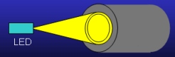
LED (Light Emitting Diode): emit infrared light at 850 nm. Used with short-distance multimode fibres. Low cost, long service life, slow modulation.
Infrared laser diodes: emit at 1,300 nm. Intermediate performance, used for medium distances.
DFB/FP lasers: wavelengths of 1,310 nm or 1,550 nm. Used with long-haul single-mode fibres and DWDM systems. Very narrow spectral bandwidth, required for dense wavelength division multiplexing.

Fig. 15-16 — Optical emitters: LED (850 nm) and laser (1,310/1,550 nm)
d) Connecteurs fibre optique
There are many different types of fibre-optic connectors. Each connector features a ferrule (a precision ceramic or metal cylinder) that holds the fibre in place and aligns it.
The most commonly used connectors:
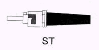
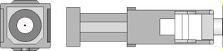
Fig. 17a-17b — ST (bayonet, left) and SC (push-pull, right) connectors
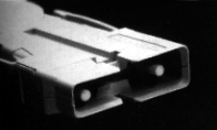
Fig. 17c — Dual MIC connector (used in FDDI networks))
|
Connector |
Fastening |
Typical use |
|
ST (Straight Tip) |
Bayonet (twist-lock) |
Multimode LAN networks |
|
SC (Subscriber Connector) |
Push-pull (clip) |
FTTH, LAN, WAN — the most common |
|
LC (Lucent Connector) |
Push-pull petit format |
SFP transceiver, datacenters |
|
FC (Ferrule Connector) |
Back |
Measuring instruments, telecoms |
|
MIC (Media Interface Connector) |
Double, clip |
FDDI (obsolete) |
|
SMA |
Back |
Military applications, instruments |
|
FCPC |
Screw-mounted with PC polishing |
Single-mode fibres |
e) Types of polishing (ferrule)
The type of polish on the optical connector (ferrule) determines the quality of the connection and the insertion loss:
· PC (Physical Contact): the end face is polished to produce a slightly domed convex surface. Reflection attenuation: −40 dB.
· UPC (Ultra Physical Contact): more pronounced curvature than PC, higher quality. Reflection attenuation: −50 dB. Blue connector.
· APC (Angled Physical Contact): convex-shaped and polished at an 8-degree angle, reducing unwanted reflections. Reflection attenuation: −60 dB. Green connector. Used in multi-subscriber FTTH (GPON) and CATV systems. This is the most recommended type of polish for long-distance links.
f) Connection techniques (coupling)
· Mechanical coupling: two connectors joined end-to-end by means of a precision adapter. Detachable connection.
· Mechanical splice: a permanent connection made by mechanical clamping. Used for repairs following a break. Insertion loss: ~0.5 dB.
· Fusion splicing: the process of joining two fibres using an electric arc (fusion splicer). The most reliable and least disruptive solution. Insertion loss: < 0.1 dB. Used for FTTH deployments and backbones.
2. Twisted-pair cables (UTP/STP/FTP)
In the simplest case, a pair of wires is used to carry the signal. The electric current generates an induced current in neighbouring lines (crosstalk), which interferes with the signal and reduces its effectiveness. Twisting the pairs cancels out this interference: the induced currents in each half-turn cancel each other out.
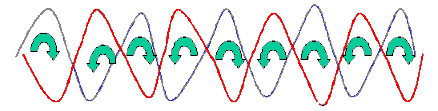
Fig. 18 — 4-pair twisted-pair UTP cable (structure and twisting of the pairs)
Twisted-pair cable comes in three main types:
UTP (Unshielded Twisted Pair): four pairs of wires enclosed in a PVC sheath. The most common, cheapest and easiest to install. Susceptible to external electromagnetic interference.
FTP (Foiled Twisted Pair): an overall aluminium shield surrounds the four pairs. Protection against electromagnetic interference (EMI) without individual shielding of the pairs.
STP (Shielded Twisted Pair): each pair is individually shielded, and the whole cable is then shielded. Maximum protection against EMI and crosstalk. A stiffer and heavier cable. Used in industrial or highly disrupted environments.
a) Cabling categories
|
Category |
Bandwidth |
Max. flow rate |
Typical use |
|
Cat 3 |
sixteen megahertz |
Ten megabits per second |
Telephony, 10BaseT Ethernet |
|
Cat 5 |
100 MHz |
One hundred megabits per second |
Fast Ethernet 100BaseTX |
|
Cat 5e |
100 MHz |
1 Gbps |
Gigabit Ethernet 1000BaseT |
|
Cat 6 |
250 MHz |
1 Gbps (10 Gbps 55 m) |
Gigabit, structured cabling |
|
Cat 6A |
500 MHz |
10 Gbps / 100 m |
10GBaseT, modern offices |
|
Cat 7 |
600 MHz |
10 Gbps |
Data centres |
|
Cat 8 |
2,000 MHz |
25–40 Gbps / 30 m |
Servers, Edge Data Centre |
💡 Choosing a structured cabling system
For new structured cabling installed in 2025, the minimum recommended category is Cat 6A, which supports 10 Gigabit Ethernet over 100 m and PoE++ (90 W). Cat 6A is mandatory in Wi-Fi 6/6E installations to avoid creating a bottleneck on the access point’s power cable.