
B. PHYSICAL INTERFACES
The interface is used to specify the connection between the terminal (DTE – Data Terminal Equipment) and the modem (DCE – Data Circuit-terminating Equipment), in terms of the circuits (number, type and function), the signals exchanged (type and form) and the connectors used.
A connection is defined by its connection interface, the connection’s characteristics and the type of connector used.
An interface has four types of properties:
Mechanical specifications: connector type, number of pins (pins).
Electrical: voltage levels, impedances, transmission modes (balanced/unbalanced).
Functional: signal assignment to pins (data, synchronisation, control, ground).
Procedural: rules governing how the interface operates — how signals are exchanged between the transmitter and the receiver.
1. RJ connectors
RJ connectors (Registered Jack) are modular interfaces standardised by the US FCC, originally for telephony, but now ubiquitous in local area networks.
a) RJ-11 connector
The RJ-11 is the standard telephone connector, with 4 pins (or 6 pins in its RJ-12 variant). It is used to connect analogue telephone lines and ADSL modems at the subscriber’s premises.
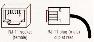
Fig. 2 — RJ-11 connector (4/6-pin configuration)
b) RJ-45 connector
The RJ-45 is the standard 8-pin network connector used for Ethernet cables (10/100/1000BaseT).The signals for a standard Ethernet connection are as follows:
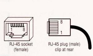
Fig. 3 — Connecteur RJ-45 (brochage 8 contacts)
|
Brooch(es) |
Signal |
function |
|
1, 2 |
TX+ / TX− |
Transmit |
|
3, 6 |
RX+ / RX− |
Receive |
|
4, 5, 7, 8 |
Unused (mass) |
10/100 Ethernet — used for PoE and Gigabit |
For ISDN BRI, the RJ-45 pinout is different: pins 1 and 2 for phantom power, pins 3, 4, 5 and 6 for transmit/receive signals, and pins 7 and 8 for earth.
c) Ethernet crossover cable
A crossover cable connects the TX pins on one end to the RX pins on the other, allowing two devices of the same type (PC to PC, switch to switch) to be connected directly without the need for an intermediate hub or switch. RJ-45 Ethernet loop: connect 1↔3 and 2↔6. Today, modern interfaces support Auto-MDIX (automatic MDI/MDI-X), making a crossover cable unnecessary.
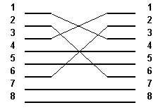
Fig. 4 — Ethernet Crossover Cable: TX/RX Crossover
2. Interface RS-530
The RS-530 (EIA-530) interface is a high-speed serial interface using a 25-pin DB-25 connector, designed to replace RS-232 in applications requiring high data rates (up to 2 Mbps). It uses differential (balanced) signalling in accordance with EIA-422, which is compatible with V.11. It allows for longer distances than RS-232 with improved immunity to interference.
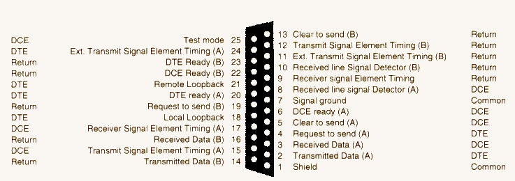
Fig. 5 — Interface RS-530 : connecteur DB-25 et affectation des signaux
3. Interface X.21
The X.21 interface is an ITU-T (CCITT) standard defining the interface between a DTE and a DCE for synchronous transmission over digital circuit-switched networks. It uses a 15-pin DB-15 connector and differential signalling. X.21 is used in particular in PDH (E1/T1) networks and as an access interface to certain Frame Relay and ISDN networks.
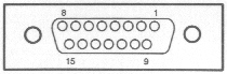
Fig. 6 — X.21 connector (DB-15, differential signalling)
4. Interface G.703
G.703 is the ITU-T recommendation defining the physical and electrical characteristics of hierarchical digital interfaces (E0 to E4, T1 to T4). It specifies signal levels, impedances and connectors for digital links at 64 kbps (G.703/G.704 E0), 2.048 Mbps (E1), 8.448 Mbps (E2), up to 139 Mbps (E4).
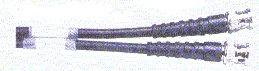
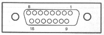
Fig. 7 — G.703 connectors (BNC coaxial and pair connector)
|
CCITT No. |
Pin |
DTE/DCE |
Description |
|
G |
8 |
— |
Signal ground |
|
T |
2 / 9 |
DTE |
Transmitted data |
|
R |
4 / 11 |
DCE |
Rx Data (received data) |
|
C |
3 / 10 |
DTE |
Control |
|
I |
5 / 12 |
DCE |
Indications |
|
S |
6 / 13 |
DTE/DCE |
Signal element timing (clock) |
5. Interface V.11
V.11 (equivalent to EIA-422) is an ITU-T standard for high-speed synchronous serial transmission (up to 10 Mbps) over balanced twisted-pair cables. It defines the electrical characteristics of digital serial interface circuits. V.11 is used in many WAN interfaces (X.21, G.703) and can operate in Tail Circuit mode (direct connection between two pieces of equipment without an intervening modem over short distances).
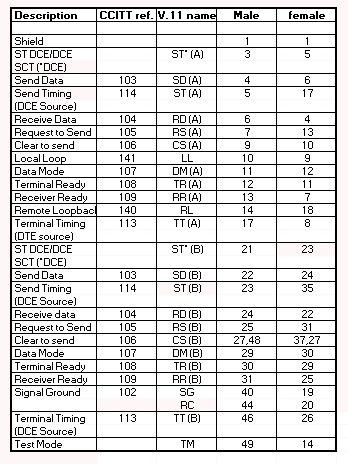
Fig. 8 — V.11 Connection Diagram in Tail Circuit Mode
6. V.24 Interface
V.24 is the ITU-T recommendation defining the communication between DTE and DCE devices for asynchronous or synchronous serial transmission, known as RS-232 in the United States. V.24 specifies the functions of the interface circuits (data, control, synchronisation) on a DB-25 or DB-9 connector. It supports data rates of up to 115,200 bps over short distances (< 15 m at full speed).
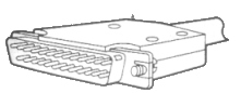
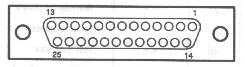
Fig. 9 — V.24/RS-232 connectors: DB-25 (a) and DB-9 (b)
ℹ V.24/RS-232 — still in use
V.24/RS-232 is considered obsolete for broadband networks but remains widely used for managing network equipment (console ports on Cisco and Juniper switches and routers, etc.), industrial systems (PLCs, SCADA), cash registers and certain medical devices. The USB-to-RS-232 adapter is a common accessory.
7. V.35 Interface
V.35 is an ITU-T standard for high-speed data transmission (up to 2 Mbps and beyond with proprietary extensions) over WAN links. It uses a 34-pin Winchester connector (block/enclosure format). V.35 has been widely used to connect routers to CSU/DSU (Channel Service Unit/Data Service Unit) equipment on T1/E1 and Frame Relay links. The official CCITT V.35 terminology is ‘Data Transmission at 48 Kbps Using 60–108 kHz Group-Band Circuits’.
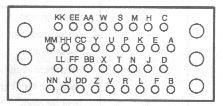
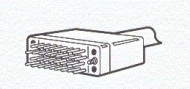
Fig. 10 — V.35 connectors (Winchester 34-pin — male and female view)
8. V.36 Interface
V.36 is an ITU-T standard for high-speed synchronous transmission (48 kbps to 168 kbps) over broadband links. It uses a 37-pin DB-37 connector and balanced (differential) signalling. V.36 is functionally similar to V.35 but uses a different connector; it is mainly used in European telecoms equipment.
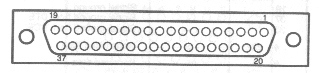
Fig. 11 — V.36 connector (DB-37)