
A. INTERCONNECTION EQUIPMENT
Equipment connected to the network that is not a host is referred to as interconnection equipment. It is given different names depending on its level of intelligence or the role it plays. Each generation of equipment corresponds to a higher level of network traffic analysis.
ℹ Overview of network equipment
The network infrastructure of a modern business relies on several complementary families of equipment. At the access level, switches connect user workstations, IP phones, Wi‑Fi access points and connected devices, often via 1 Gbit/s ports powered by PoE. Further up the stack, aggregation switches and routers handle inter-VLAN routing, interconnection with the WAN and the enforcement of security policies (access control lists, QoS, filtering). Dedicated firewalls, Wi-Fi controllers and specialised appliances (VPN, proxy, IDS/IPS) complete the setup to secure data flows and monitor the overall operation of the network.
1. Repeater
Repeaters operate at Layer 1 of the OSI model (physical layer). They connect two segments together, read the electrical pulses at their input for a given type of medium (fibre optic, coaxial, twisted pair) and generate reshaped and amplified pulses, following clock regeneration and resynchronisation.
Functions of the repeater:
· Allows the network length to be extended beyond 500 m per section (up to four repeaters between two nodes) without any significant deterioration in signal quality.
· Amplifies and regenerates the digital signal.
· Isolates a faulty section (partitioning) — for example, in the event of a cable break.
· Converts between two different Ethernet media (fibre, coaxial, and Thick Ethernet to Thin Ethernet).
ℹ Collision domain
All segments connected to a repeater form part of the same collision domain. This means that a collision on one segment propagates to all connected segments. The repeater therefore does not provide any logical segmentation of traffic.
The causes of signal degradation that the repeater corrects are: distance, losses due to propagation delay, electromagnetic interference, the type of cable and bandwidth.
Common uses of repeaters: coaxial Ethernet networks (10Base5, 10Base2), hubs (10/100BaseT multi-port repeaters), Token Ring networks (where each computer acts as a repeater by passing the token to the next one).
⚠ Repeaters — legacy equipment
Standalone repeaters and hubs (multi-port repeaters) have been almost entirely replaced by switches in modern networks. The use of coaxial repeaters has become rare with the disappearance of coaxial cabling in LANs. Signal repeaters are still found in long-distance links (telecoms, amplified fibre optics — EDFA amplifiers).
2. Bridge
Bridges operate at layer 2 of the OSI model (data link layer). They either keep messages on one segment or forward them to another, depending on the source and destination addresses contained in the frames. In particular, they enable two networks with the same physical architecture to be interconnected whilst segmenting the collision domains.
There are two main filtering algorithms:
Spanning Tree (Ethernet): the bridge monitors the networks connected to each of its ports and builds a table of MAC addresses (Layer 2) for all connected stations. It forwards frames only to the port where the destination is located. Routing in a multi-bridge network is achieved through the exchange of BPDUs (Bridge Protocol Data Units) between bridges: these frames enable all bridges to identify one another, elect a Root Bridge (maximum priority), designate backup bridges and avoid loops. This protocol is the predecessor of STP/RSTP/MSTP, which is covered in the LAN section.
Source Routing (Token Ring): To identify the most efficient route, the bridge transmits specific "route discovery" frames. Compatible intermediate bridges insert routing information into these frames. The first frame to return to the sender describes the most efficient route, and this information is then inserted into every data frame.
Bridges enable traffic to be segmented (segmentation) and prevent interference and collisions between segments. Broadcast frames, however, are transmitted across all segments. Bridges are transparent to higher-level protocols. Some hybrid bridges (BROUTER) use proprietary protocols that allow traffic to be shared across multiple links simultaneously (load balancing).
ℹ Bridge transparent
As a bridge does not have its own MAC address visible on the network (it is transparent), it must store the addresses of all connected stations. Its memory must be sized accordingly. Bridges separate collision domains but not broadcast domains — that role is performed by routers.
3. Routers
Routers operate at Layer 3 of the OSI model (network layer) and are responsible for routing data units (IP datagrams). They enable networks of different types to be interconnected. It is the most sophisticated tool for routing data: a router is virtually a computer in its own right, capable of decoding frames to identify the destination IP address and directing the information in the right direction.
In a network interconnection, where each network has its own identity, security is crucial. Incoming and outgoing data must be filtered according to their source and destination. Depending on the complexity of the network to be protected, designing and maintaining these controls can be more or less difficult.
a) Routing
Routing determines where to send a datagram.
A routing system comprises three fundamental processes:
· The host machine must know when and how to communicate with a router (default gateway).
· The router must be able to determine a path to the remote network (routing table, routing protocols).
· The router on the destination network must be able to connect to the host machine.
· A routing protocol performs the following tasks:
· Describe the cost of a route based on the metrics (number of hops, bandwidth, delay, reliability).
· Supports multiple active routes between two networks (load balancing, failover routes).
· Ensure that routing information is propagated correctly between routers.
· Reduce network traffic associated with the routing protocol itself (fast convergence).
· Manage security features to protect against spoofed requests (route poisoning, MD5/SHA authentication).
b) General operation
Routers operate using logical IP addresses. They communicate with one another and can exchange information with other devices or stations. As the number of networks grows, the router’s task becomes more complex.
As routers connect networks of different types, the main challenge lies in this reliance on protocols. Multi-protocol routers have emerged, capable of supporting a wide variety of protocols within a single device. Modern routers are capable of routing IP, MPLS, and various encapsulated Layer 2 protocols.
c) Types of routing
A distinction is made between static routing (manually configured tables, which are simple but do not adapt to failures) and dynamic routing.
Two major dynamic routing algorithms:
Distance Vector — RIP (Bellman-Ford): based on the number of hops (best route = minimum number of hops). Each router knows the number of hops to each destination through the exchange of information with its direct neighbours (RIP v1/v2, EIGRP). Simple but slow to converge and limited to 15 hops (RIP).
Link State — OSPF: determines the best route based on link cost (bandwidth, delay). Each router builds a complete map of the network topology (LSDB — Link State Database) by exchanging LSAs (Link State Advertisements). Fast convergence, no hop limit, supports hierarchies (OSPF zones). The most widely used open standard protocol in enterprise networks.
BGP (Border Gateway Protocol): an inter-domain routing protocol used on the Internet for the exchange of routes between operators (AS — Autonomous System). It is the protocol that keeps the global Internet running.
d) Routing tables
IP routing algorithms use an Internet routing table (IP Routing Table) on each machine. This table contains information about the various possible destinations and how to reach them. Whenever the IP software on a gateway or machine needs to transmit a datagram, it consults the routing table to determine where to send it.
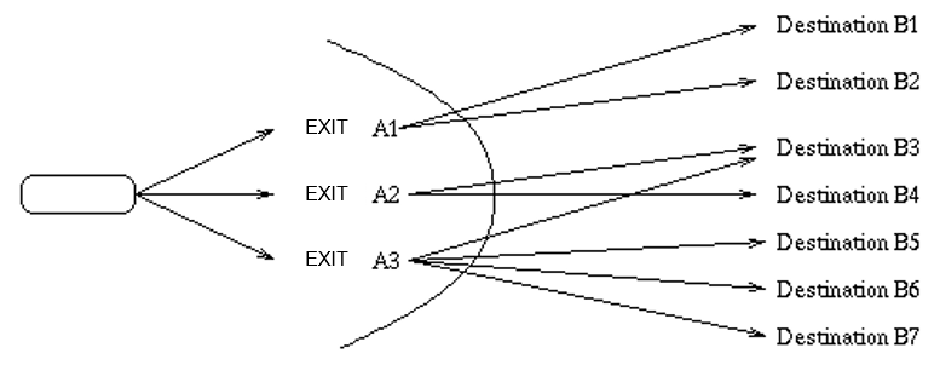
Fig. 1 — Example of a routing table: a packet destined for B6 takes exit A3
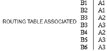
Routing tables contain network addresses but not all IP addresses, for reasons of memory space and ease of updating. If no specific route is found in the table for a destination, the routing procedures send the datagram to a default gateway.
e) Centralised routing vs distributed routing
Centralised routing: a central node receives information from all network components and generates routing tables using specific algorithms. Its criteria may include: link cost, required bandwidth, transit time, number of nodes to traverse, security, and memory usage. Simple to manage but has a single point of failure (SPOF).
Distributed routing: each router calculates its routes independently by exchanging information with its neighbours. This is the principle behind RIP, OSPF and BGP. The asynchronous transmission of tables (as soon as a significant change is detected) allows for near-real-time updates, at the cost of an additional load on the network (control packets).
f) Technical specifications
A router requires a routing table stored in RAM (DRAM/SRAM) for fast access and on disk or flash storage for persistence.
The technical specifications of the routers vary depending on the range:
Access routers (SMB/SOHO): 1–4 WAN/LAN interfaces, data rates of 100 Mbps–1 Gbps, NAT functionality, built-in firewall, optional Wi-Fi.
Enterprise (edge) routers: 4–24 interfaces, throughput 1–10 Gbps, MPLS support, IPsec/SSL VPN, advanced QoS.
Core routers: 10–400 Gbps per port, hardware switching (ASICs/FPGAs), several Tbps of total switching capacity. Examples: Cisco ASR 9000, Juniper PTX.
⚡ Virtual routers and SD-WAN
Network virtualisation has given rise to software routers (vRouter): software instances that can run on standard (x86) servers or in the cloud. SD-WAN (Software-Defined WAN) decouples the control plane from the data plane, enabling centralised management of routing policies across heterogeneous WAN links (MPLS, 4G/5G, Internet). The main SD-WAN solutions are Cisco Viptela, VMware VeloCloud, Fortinet and Cato Networks.
4. Gateways
The term ‘gateway’ is a generic term referring to equipment operating at Layer 3 or above. It enables the ‘intelligent’ interconnection of heterogeneous networks by converting messages from one network format to another in both directions.
Depending on the context, a gateway may refer to:
A protocol gateway: converts protocols between two networks of different types (e.g. an SNA/IP gateway to interconnect IBM mainframes with TCP/IP networks).
An application gateway (proxy): operates at Layer 7, examines the content of data exchanges to perform specific processing (inspection, filtering, caching, translation).
A VoIP (Voice over IP) gateway: converts traditional telephone calls (PSTN) into IP packets and vice versa.
An IoT gateway: aggregates data from sensors (Zigbee, Z-Wave and LoRa protocols) and transmits it to the internet via IP.
5. Hubs
A hub (Host Unit Broadcast), also known as a concentrator, is a small device that allows several computers to be connected to one another via RJ-45 Ethernet cables. Hubs form the centre of star-shaped configurations and ensure that the various branches are interconnected.
A hub can be thought of as an electrical ‘prism’: all packets transmitted on a segment or by a device connected to one of the ports are forwarded to all the other ports. Hubs do not examine the contents of the frames; they simply repeat the information. As they do not analyse the content, they operate at Layer 1 (Physical) of the OSI model.
Practical implications: all ports on a hub share the same collision domain; bandwidth is shared among all connected devices; and performance deteriorates rapidly as the number of users increases.
⚠ Hubs — obsolete equipment
Hubs have been completely replaced by switches in modern networks. It is now impossible to buy a new 10/100 Mbps hub for business use. USB hubs (which share USB bandwidth) remain common for peripherals, but they work differently from network hubs.
6. Switches
The key difference from a hub is that a switch knows which computers are connected to each of its ports. So, if it receives a data packet intended for computer X, it sends it only to computer X and not to the others. It routes the incoming data to the output port connected to the relevant computer.
Switches analyse the contents of the frame, identify the destination MAC address and send the frame to the correct port. This MAC/port mapping table is built dynamically through self-learning (MAC address table or CAM table).
Technical specifications of the switches:
· Operate at layer 2 (L2 switch) or layer 3 (L3 switch / router switch) of the OSI model.
· Each port constitutes a separate collision domain: no more collisions between ports.
· They can be auto-sensing 10/100/1000/10000 Mbps with automatic duplex negotiation.
· These allow you to configure VLANs (Virtual LANs) to logically segment the network.
· Support link aggregation (LACP 802.3ad) to increase bandwidth or provide redundancy.
· Layer 3 switches can route traffic between VLANs without going through an external router (inter-VLAN routing), making them versatile pieces of equipment in the core of an enterprise network.
⚡ Modern switches and SDN
Modern switches support switching capacities ranging from several hundred Gbps to several Tbps (Tbps backplane). SDN (Software-Defined Networking) decouples the control plane from the data plane: the OpenFlow switch becomes a simple forwarding device controlled by a centralised controller (OpenDaylight, ONOS). This approach is widely used in data centres (spine-leaf architecture) and cloud operators’ networks (hyperscalers).
7. Enterprise network architectures
a) Architecture access / distribution / core
In a business setting, traditional network architecture is organised into three hierarchical layers. The access layer directly connects workstations, IP phones and Wi-Fi access points; it manages VLANs, PoE and port-based security policies. The distribution layer aggregates the access switches on a floor or in a building, handles inter-VLAN routing and enforces quality of service policies. The core layer provides high-speed transport between distribution blocks and to data centres or internet access points, with absolute priority given to availability and performance.
b) Architecture leaf-spine en datacenter
In data centres and private cloud infrastructures, the three-tier hierarchical model is giving way to the leaf-spine architecture, which is better suited to east-west traffic (server-to-server) that dominates virtualised and containerised workloads. Each leaf switch (server access) is connected to all spine switches (core) without exception, ensuring a maximum of two hops between any two servers and eliminating bottlenecks associated with vertical aggregation. This topology also facilitates horizontal scaling: adding capacity simply involves connecting a new leaf to all existing spines, without restructuring the entire network.