
H. BROADBAND NETWORKS
The history of networks and telecommunications could be summed up as a never-ending race for speed. A network is considered high-speed if its speed is at least 100 Mbps, whilst ultra-high-speed networks reach and exceed 1 Gbps. With such speeds, it is capable of transmitting all types of information: data, text, graphics, photos, images, animations, videos and audio. For ‘real-time’ applications (voice, video), the high-speed network must be capable of supporting isochronous streams.
Several ‘broadband’ technologies are or have been in widespread use:
FDDI (Fibre Distributed Data Interface): a standard defining the first two layers of the fibre transport architecture, operating at 100 Mbps in a ring configuration. Obsolete.
DQDB (Distributed Queue Dual Bus): a standardisation project for metropolitan area networks (MAN). History.
Switched Ethernet: the leading solution for high-speed networks, ranging from 100 Mbps to 400 Gbps.
ATM (Asynchronous Transfer Mode): a cell-switching technology that supports broadband ISDN networks. See section E.
SDH/SONET (Synchronous Digital Hierarchy / Synchronous Optical Networks): the physical transport layer for very high-speed optical networks.
Broadband TCP/IP: the recommended solution for high-speed IP connections. IP routing can now reach several Tbps in core network routers.
1. Ethernet (IEEE 802.3)
Historically, it was the first local area network and remains the most widely used. Ethernet is a local area network architecture designed by Xerox, which was subsequently standardised as IEEE 802.3 in 1980 by Xerox, Intel and Digital. Its principle is based on the broadcasting of messages over a logical bus (which may be a physical bus or star topology) where all hosts share the medium equally, using the CSMA/CD protocol.
The Ethernet architecture consists of two fundamental layers: the physical layer and the data link layer, which correspond to layers 1 and 2 of the OSI model respectively.
The media used are: coaxial cable (traditional), UTP twisted-pair cable (
The main Ethernet standards:
|
Standard |
Flow rate |
Support |
Distance max. |
|
Ten-Base-T |
Ten megabits per second |
UTP Category 3 |
100 m |
|
100Base-TX |
100 Mbps (Fast Ethernet) |
UTP Category 5 |
100 m |
|
100Base-FX |
One hundred megabits per second |
Fibre MMF |
1,000 m |
|
1000Base-T |
1 Gbps (Gigabit Ethernet) |
UTP Cat. 5e/6 |
100 m |
|
1000Base-SX |
1 Gbps |
Fibre MMF |
550 m |
|
10 Gigabit Base-T |
10 Gbps |
UTP Cat.6a |
100 m |
|
10 Gigabit Short Reach |
10 Gbps |
Fibre MMF |
300 m |
|
25GBase-T |
25 Gbps |
Fiber / Cat. 8 |
30 m |
|
100 Gigabit Short-reach 4-lane |
100 Gbps |
Fibre MMF |
100 m |
|
400 Gigabit Short-reach Serial |
400 Gbps |
Fibre MMF |
100 m |
2. Ethernet FRAME
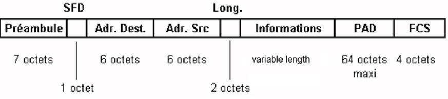
Fig. 8 — Ethernet Frame Format (IEEE 802.3)
Meaning of the fields in an Ethernet frame:
· Preamble (7 bytes): a sequence of alternating 1s and 0s used to synchronise the receiver with the transmitted frame.
· SFD (Start Frame Delimiter, 1 byte): the sequence 10101011, which marks the start of the usable data.
· Destination address (6 bytes): the physical (MAC) address of the station that is to receive the frame. Broadcast if all bits are set to 1 (broadcast: FF:FF:FF:FF:FF:FF).
· Source address (6 bytes): the Ethernet address of the station that transmitted the frame.
· Type or length (2 bytes): type of encapsulated protocol (0x0800 = IPv4, 0x0806 = ARP, 0x86DD = IPv6, 0x8100 = 802.1Q VLAN) or frame length for Ethernet II.
· Information / Data (46 to 1,500 bytes): data from the LLC sublayer.
· PAD: meaningless padding bytes, inserted if the frame is too short (minimum 64 bytes in total).
· FCS — Frame Check Sequence (4 bytes): the result of a CRC calculation performed on the frame; used to detect bits that have been corrupted during transmission.
3. Switched Ethernet
With shared Ethernet (hub), every message sent is received by all connected machines and the available bandwidth is shared. With switched Ethernet, the physical topology remains star-shaped but is organised around a switch (switch). The switch uses a filtering and switching mechanism: it inspects the source and destination addresses of messages, creates a table that allows it to know which machine is connected to which port (self-learning), and then transmits the message only to the appropriate port.
As a result, each data transfer can take place at the nominal data rate (no more bandwidth sharing), without collisions, leading to a significant improvement in performance (at the same nominal speed). As switching eliminates collisions and 10/100/1000 Base-T links have separate circuits for transmission and reception (one pair per direction), modern switches operate in full-duplex mode on their ports.
Full-duplex mode is particularly useful for servers that need to serve multiple clients simultaneously. Furthermore, as outgoing and incoming traffic is no longer transmitted on all ports, it becomes much more difficult to eavesdrop (sniffer) on the network, which contributes to overall security.