
C. THE PROTOCOLS
For data transmission to take place correctly between two devices (whether they are DTE (Data Terminal Equipment) or DCE (Data Circuit-Terminating Equipment)), every link in the chain must follow predefined procedures or conventions that form the basis of the communication. These conventions are referred to as a protocol.
The protocol defines the synchronisation between transmitter and receiver, the priority rules, how transmission errors will be detected and corrected, the procedures to be followed in the event of a fault, and how data streams are adapted to the channel bandwidth. Protocols can be implemented in any type of equipment, either in hardware or software form.
1. X.25 packet switching
The X.25 specification originated with telephone operators. It defines a Layer 3 protocol designed to manage virtual circuits and based on the following characteristics:
· Management of user addressing, including the ability to multiplex communications over a single physical link.
· Establishment and release of virtual circuits (PVC and SVC).
· Error and failure handling at each intermediate node.
· Flow control on each circuit, packet fragmentation and reassembly.
X.25 is being used less and less because it is not suited to high data rates and fibre optics. The X.25 specification defines a point-to-point interaction between data processing terminal equipment (ETTD) and data circuit termination equipment (ETCD). A DTE is connected to a DTE via a translation unit known as a packet assembler/disassembler (PAD: Packet Assembler/Disassembler).
End-to-end communication between ETTDs takes place via a virtual circuit. Virtual circuits enable communication between separate network elements, via any number of intermediate nodes, without the need to dedicate fixed portions of the network to the connection. Virtual circuits preserve packet order, support full-duplex communication, use flow control and allow multiplexing.
There are two types of virtual circuits:
PVC (Permanent Virtual Circuit): a permanent logical path to the network between the source and its destination. Once the logical path has been established under normal conditions, all packets follow it. In the event of a failure, a new path is negotiated. PVCs are generally used for the most frequent data transfers.
SVC (Switched Virtual Circuit): does not establish a permanent logical circuit. Each packet finds its own path to the destination by using the best route available at that moment. With this method, packets follow different routes and may therefore arrive at their destination in the wrong order. X.25 must take this situation into account to ensure error-free transmission. SVCs are used for sporadic data transfers.
As the packets are fragmented, it would be cumbersome to carry the full address in each fragment. A logical channel number linked to the virtual path has therefore been defined. Each logical channel is identified by a logical channel group (encoded using 4 bits) and a logical channel number (encoded using 8 bits).
During data transfer, X.25 uses a protocol called LAPB to ensure that frames arrive at their destination in the correct order and without errors. Large buffers are used to cope with peaks in demand and to verify the integrity of the data at every stage of its journey. This ‘store and forward’ technique and constant error checking result in significant delays.
⚡ Why X.25 limits the data rate to 9,600 bps per virtual circuit
The high error rates on the copper links of the time necessitated a highly error-checking protocol that severely limited data rates. Over long distances, a packet had almost no chance of arriving intact at the other end. Switches therefore had to communicate with one another to exchange frames (RR: Receive Ready, RNR: Receive Not Ready, REJ: Reject). This dialogue protocol, applied at layers 2 and 3, consumed a significant portion of the bandwidth. Furthermore, X.25 segments packets and reassembles them on arrival. All this error handling slows down the data rate, which is limited to 9,600 bps per virtual circuit and 2 Mbps per line.
⚠ X.25 — completely obsolete
X.25 is now completely obsolete in data networks. The last public X.25 networks in France (Transpac) were shut down between 2012 and 2014. It survives only in a few legacy industrial or banking systems.
2. Frame Relay
Frame Relay is one of the protocols that operate at the link layer (Layer 2) of the seven-layer model. It has very low overhead, none of the error correction features of X.25, and very limited flow control. Frame Relay is simpler and more straightforward, resulting in better performance and efficiency.
Frame Relay enables the statistical multiplexing of numerous logical data connections over a single physical link, resulting in a more efficient use of available bandwidth. This protocol relies heavily on fibre optics and digital transmission. Over such links, the protocol can delegate error checking tasks to higher layers.
Like X.25, Frame Relay is based on the establishment of a virtual circuit. As error rates have fallen from 10⁻⁵ to 10⁻⁸ thanks to fibre optics, the protocol has been simplified. Frame Relay no longer performs segmentation or error checking between switches. The only remaining check is the CRC (Cyclic Redundancy Check) performed at the hardware level. In the event of an incorrect CRC, the switch simply discards the frame without warning. Error handling is carried out directly at the stations in the upper layers.
The main advantage of Frame Relay is that, as with X.25, customers pay for the data rate (CIR — Committed Information Rate), rather than for the link speed. The overall cost is proportional to the value of the guaranteed data rate.
⚠ Frame Relay — obsolete
Frame Relay was widely deployed in the 1990s and 2000s for corporate WAN links, particularly for connecting sites. It was gradually replaced by MPLS and then by SD-WAN from the 2010s onwards. It is now obsolete.
3. TCP/IP (IPv4)
Faced with a proliferation of devices using different and incompatible communication protocols, the US Department of Defense (DOD) decided to define its own architecture. This architecture formed the basis of the Internet. IPv4 is the original version of TCP/IP and remains the most widely deployed today, although IPv6 is steadily gaining ground.
TCP/IP is often regarded as a complete architecture. Strictly speaking, it consists of two protocols:
IP (Internet Protocol): a network-layer protocol that provides a connectionless service.
TCP (Transmission Control Protocol): a transport-layer protocol that provides a reliable, connection-oriented service.
In a broader sense, the TCP/IP family also includes FTP (file transfer), SMTP (email), Telnet (terminal emulation), HTTP/HTTPS (web), DNS, and many other application protocols.
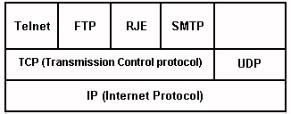
Fig. 2 — Layered TCP/IP architecture
ℹ IP addressing on WAN links
On WAN links, IPv4 addresses are generally public addresses or private addresses used within an operator’s network, often with address translation (NAT) mechanisms at the edge of the Internet. In IPv6, routes between sites use global prefixes provided by the operator or by the company itself, which allows traffic to be routed without NAT. The choice of addressing scheme (private IPv4 + NAT, dual IPv4/IPv6 stack, IPv6‑only with transition mechanisms) has a direct impact on the simplicity of routing and the ability to expose services to the outside world
a) IP — Internet Protocol
The Internet Protocol (IP), which corresponds to layer 3 of the reference architecture, is the most fundamental part of the Internet. To send data over the Internet, it must be ‘packaged’ into IP packets, known as datagrams.
The IP Protocol operates in a connectionless mode: the sender transmits its packets without taking the receiver’s status into account, provided the receiver is present. There is no connection establishment or termination, nor is there any flow control. The main functions of the IP Protocol are the connectionless transmission of datagrams, data routing, and the fragmentation and reassembly of data.
In addition to the data, IP packets consist of a header containing the sender’s and recipient’s IP addresses, as well as a checksum determined by the data contained in the packet, which allows the recipient to determine whether the packet has been corrupted during transmission.
Packets are independent of one another and are routed individually across the network by each switch (router). The security provided by this protocol is very limited — there is no detection of lost packets, nor any error recovery mechanisms. In fact, the reason IP does not verify that data has been received correctly is that the upper layer (TCP) handles this, with the two layers together ensuring reliable transmission. Part of the IP protocol corresponds to the ICMP protocol (RFC 792).
This control protocol performs the following functions:
· Flow control: when datagrams arrive too quickly, the destination sends a congestion message.
· Detection of an unreachable destination: when a destination is found to be unreachable, the system sends an ‘unreachable destination’ message to the source.
· Route redirection: a gateway sends a redirection message to instruct a host machine to use a different gateway.
· Checking remote hosts: a host can send an ICMP echo request (ping) to verify that the Internet Protocol on the remote system is operational.
b) IPv4 addresses
One of the most interesting features of the TCP/IP protocol is that it assigns a fixed number to every computer connected to the Internet; this number is known as the IP address. It is a logical address, distinct from the physical addresses of network interface cards (MAC addresses). In the IPv4 version, addresses are encoded using 32 bits. Thus, every computer on the Internet is assigned an address of the form a.b.c.d (where a, b, c, d are numbers between 0 and 255), for example 192.168.1.1. For the computer, this IP address is encoded in binary (4 x 8 bits = 32 bits). e.g.: The address 192.168.1.1 corresponds to 11000000.10101000.00000001.00000001 in binary.
📄 Decoding an IP address
The address 202.15.170.1 is broken down into four bytes: 202 = 11001010, 15 = 00001111, 170 = 10101010, 1 = 00000001. It is easier for us to remember 202.15.170.1 than 11001010000011111010101000000001. The first two bytes identify the network, and the last two identify the host on that network (for a Class B address).
c) IPv4 address classes
Addressing is logically structured within a network and subnet architecture. IP addresses are governed by an international body (IANA, followed by the regional RIRs), which allocates the various network classes. There are five classes, the primary purpose of which is to divide the address into a network portion and a host portion.
Class A(126 networks, up to 16,777,214 hosts): first bit set to 0, first octet between 1 and 126.

Class A is characterised by an 8-bit network address where the first bit is set to 0 (first octet less than 128). Class A addresses are of the form rrr.hhh.hhh.hhh, with 7 bits for the network number and 24 bits for the local address (ranges 1.0.0.0 to 126.0.0.0). There are a small number of Class A networks, but each can contain up to 16 million machines.
Class B(16,384 networks, up to 65,534 hosts): the first two bits are 10, and the first octet is between 128 and 191.

Class B is characterised by a 16-bit network address, the first two bits of which are 10. Class B addresses are of the form rrr.rrr.hhh.hhh, with 16 bits for the network (128.1.0.0 to 191.255.0.0) and 16 bits for the hosts (i.e. 65,534 possible hosts). There are thousands of Class B networks.
Class C(2,097,152 networks, up to 254 hosts): first three bits set to 110, first octet between 192 and 223.

Class C is characterised by a 24-bit network address, the first three bits of which are set to 110. Class C addresses are of the form rrr.rrr.rrr.hhh, with 24 bits for the network (192.0.1.0 to 223.255.255.0) and 8 bits for the hosts (254 possible local addresses). It is possible to envisage millions of Class C networks, each comprising no more than 254 stations.
Class D(multicast addresses): networks 224 to 239, e.g. 224.4.4.4. Point-to-multipoint transmissions (videoconferencing, multicast streaming). No network/host structure.
Class E(reserved for experimental use): networks 240 to 255. Not used in production.
ℹ Reserved addresses
For each address class, certain addresses are reserved. The address 0 in Class A defines the default gateway, and the address 127 is associated with the loopback address (127.0.0.1). In all classes, the addresses 0 and 255 are reserved for network and broadcast addresses. The address 255.255.255.255 represents a universal broadcast address.
d) Subnet masks and CIDR
To allow for maximum flexibility in how IP addresses are divided into subnets, the TCP/IP subnetting standard allows the interpretation of subnets to be chosen independently for each network. Once a subnetting scheme has been chosen, all machines on the network must comply with it.
Subnetting divides a network address into several unique subnet addresses, so that a specific address can be assigned to each physical network. The subnet mask is a 32-bit number in which the bits set to 1 denote the network portion and the bits set to 0 denote the host portion.
📄 Subnet mask
For a network with the address 192.168.1.0 and a /24 subnet mask (255.255.255.0), there can be 254 hosts. With a /25 subnet mask (255.255.255.128), the network is divided into two subnets of 126 hosts each: 192.168.1.0/25 and 192.168.1.128/25. The CIDR (Classless Inter-Domain Routing) notation, such as /24 or /25, indicates the number of bits in the network mask.
⚡ RFC 1918 private addresses
Certain IPv4 address ranges are reserved for private networks (not routed on the Internet) by RFC 1918: 10.0.0.0/8 (private Class A), 172.16.0.0/12 (private Class B, i.e. 172.16.x.x to 172.31.x.x) and 192.168.0.0/16 (private Class C). These addresses are used in corporate LANs and home networks. The NAT (Network Address Translation) mechanism allows machines with private addresses to access the Internet via a single public address.
e) TCP — Transmission Control Protocol
The TCP protocol (Transmission Control Protocol) is undoubtedly regarded as the most important transport-layer protocol, encompassing the Layer 4 functions of the reference model. TCP operates in connection mode, unlike UDP, which also operates at the transport layer but in a connectionless mode and with virtually no reliability features. TCP was developed to ensure reliable communication between two hosts on the same physical network or across different networks.
Features of TCP:
· De facto (de jure) protocol, with all the benefits that this entails, including the availability and independence of the hardware or operating system.
· Transparency regarding the hardware used, meaning it can be used on Ethernet networks, Wi-Fi, dial-up connections or dedicated lines.
· Universal addressing, which makes it possible to contact both a station on the same local network and a station connected to the Internet on another continent.
TCP is responsible for breaking the data stream transmitted by the upper layer into segments. To prevent any loss of information, TCP uses a positive acknowledgement mechanism with retransmission. This mechanism involves a station wishing to send a packet sending it at regular intervals until it receives a positive acknowledgement. TCP uses a sequence number to identify each segment in order to avoid duplication. The maximum number of segments that a receiving station is permitted to receive without issuing an acknowledgement is called a ‘window’.
f) Format of a TCP segment
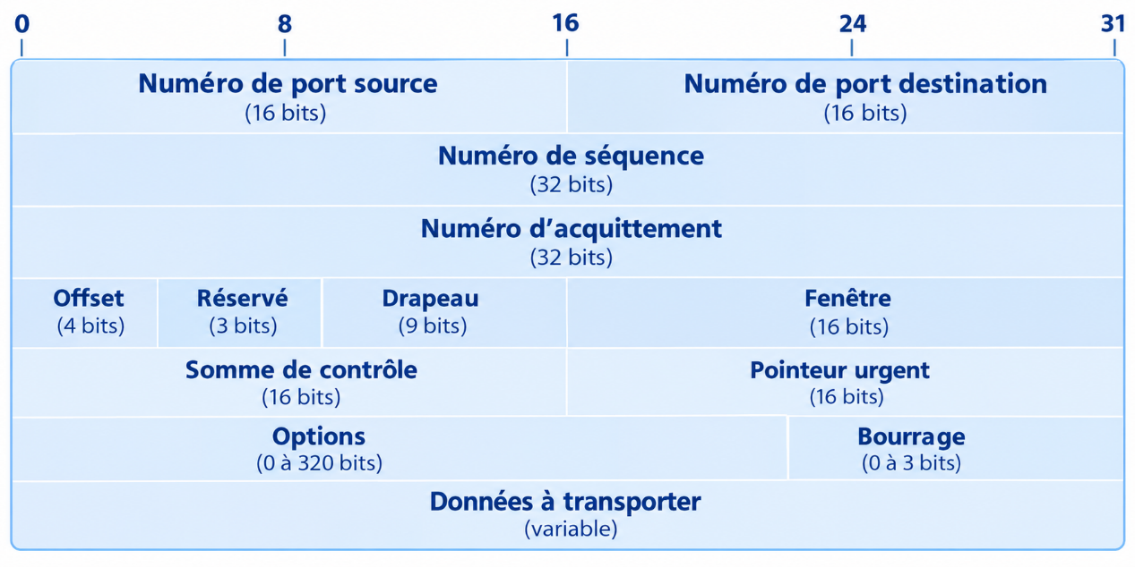
Fig. 3 — Format of a TCP segment
Meaning of the fields in the TCP segment:
· Source and destination port numbers: 16-bit integers that identify the communication endpoint (ports below 1,024 are reserved for well-known services).
· Sequence number (32 bits): used to restore the order of received packets and filter out duplicate packets. This number is incremented by one each time a byte is sent.
· ACK number (32 bits): if the ACK flag is set, this field specifies the next expected sequence number. It serves as an acknowledgement of all segments with a lower sequence number.
· Data offset (4 bits): indicates the number of 32-bit words in the TCP header (minimum value 5, maximum value 15, i.e. 20 to 60 bytes of header).
· Flags (flags, 9 bits): URG (urgent), ACK (acknowledgement), PSH (immediate push), RST (connection reset), SYN (synchronisation during connection establishment), FIN (end of connection).
· Window (16 bits): the number of bytes available in the receive buffer, i.e. the number of bytes that can be received before an acknowledgement is sent.
· Checksum (16 bits): integrity check of the header and data.
· Urgent pointer (16 bits): valid if the URG flag is set. Pointer to the urgent data byte.
· Options and padding: optional fields used to align the header to 32-bit words.
⚡ Establishing and closing a TCP connection
A TCP connection is established through the exchange of three messages (three-way handshake): SYN (client→server), SYN-ACK (server→client), ACK (client→server). Closing the connection involves four messages (four-way close): FIN (initiator), ACK, FIN (respondent), ACK. This mechanism ensures that both ends agree to open and close the connection.
g) UDP — User Datagram Protocol
UDP (User Datagram Protocol) is a transport layer protocol, just like TCP. Unlike TCP, it is unreliable and operates in a connectionless mode. It provides error detection but no error recovery. It does not use acknowledgements to ensure that data has been correctly received, does not resequence received messages, and does not provide a flow control mechanism. UDP datagrams may therefore be lost, duplicated or out of sequence.
Nevertheless, UDP’s greatest strength lies in its simplicity. The absence of a connection mechanism significantly speeds up data exchange. UDP performs very well and efficiently on local area networks, which are highly reliable and minimise the risk of errors. UDP is particularly well suited to real-time applications (Voice over IP, video conferencing, streaming, DNS) where low latency takes precedence over reliability.
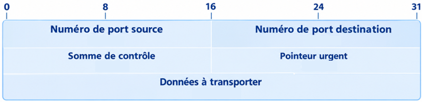
Fig. 4 — Format of a UDP datagram (4 fields: source port, port dest., length, checksum)
h) ARP and RARP protocols
The physical addresses (MAC) of the hosts are stored in PROM on the network interface cards, whilst the logical addresses (IP) are stored in files on the hard drives. Within the same physical network (or subnet), two machines can only communicate if they know each other’s physical addresses. It is therefore necessary to establish a mechanism for mapping these physical (MAC) and logical (IP) addresses.
ℹ ARP over an Ethernet network
In an Ethernet network, a host’s Ethernet address is stored as 6 bytes (48 bits), whereas its Internet address is stored as 4 bytes (32 bits). The Address Resolution Protocol (ARP) converts the 32-bit logical address into a 48-bit physical address.
How the ARP protocol works: Host A wants to send a message to host B, but only knows B’s IP address. A sends a broadcast message over the network containing its own IP and MAC addresses, and B’s IP address. Only host B recognises its IP address and responds by sending its MAC address to A. As broadcasting is resource-intensive, each host maintains an ARP cache containing a table mapping recently acquired addresses.
How the RARP protocol works: A host on the network that wishes to obtain its logical address sends a RARP message containing its physical address as a broadcast. An address server configured for this purpose returns the corresponding logical address to the station. This protocol is used only by hosts that do not have information about their logical address (for example, disk-less stations). RARP has now been replaced by DHCP.