
B. THE OSI MODEL
In 1977, the International Organisation for Standardisation (ISO) established, for the sake of compatibility between different machines, a set of rules governing the various layers, known as the OSI model (Open System Interconnection model). This is known as the OSI reference model because it deals with the connection between open systems (with other systems).
The OSI model proposes dividing communication into seven layers, in order to standardise the methods of exchange between two systems. Each layer has a specific role and communicates on request (on demand) from the layer above it, using services from the layer below (except for the physical layer).
The data transferred by the services are SDUs (Service Data Units). The exchange of information follows a protocol with corresponding layers. The data transferred via this protocol are PDUs (Protocol Data Units).
This layered structure was designed to greatly simplify the overall understanding of the system and to facilitate its implementation. It should be possible to replace one layer with another layer at the same level, without having to change the other levels. The interfaces between layers must be adhered to in order to preserve the simplicity of the architecture.
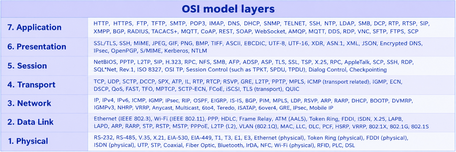
Fig. 1 —OSI Model Layers (Source : Wikipédia)
The model comprises seven layers. The first four layers are the network layers: they physically transmit data from one application to another, without error. The other three are responsible for formatting the information and providing multiple access routes to the same application.
1. The Application Layer (C7)
The purpose of this layer is to provide services to network users. It is this layer that contains the computer application (the programme) that wishes to communicate with a remote computer. It is at this level that we find programmes for file transfer, terminal emulation, remote job submission, email exchange, etc. Protocols at this layer include HTTP/HTTPS, FTP, SMTP, DNS, SNMP, SSH, Telnet and RDP.
2. The Presentation layer (C6)
It provides a representation of data (a representation that is independent of computers, operating systems, etc.) and includes services such as encryption, compression and data formatting. Indeed, there are many different ways of encoding information in computing, depending on the hardware and software used.
· There are various character encoding schemes (ASCII, EBCDIC, UTF-8, Unicode, etc.).
· Numbers can be encoded using different numbers of bytes.
· The high-order and low-order bytes may be arranged in different orders (endianness: big-endian or little-endian).
3. The Session layer (C5)
This layer enables communication to be organised into independent units. It also provides a control structure for communication between applications. It establishes, maintains and terminates sessions between applications. One of the key strengths of this layer is security.
Organisation of exchanges:
· Right of speech: half-duplex (one at a time) or full-duplex (simultaneous).
· Concept of an activity: it can be started, stopped, paused or resumed.
· Checkpoints enabling disaster recovery.
ℹ Session layer
The session layer is also the first part of the network architecture outside the communication itself. In practice, in the TCP/IP model, the session and presentation layers are combined into the application layer.
4. The Transport Layer (C4)
It is responsible for establishing connections, maintaining connection quality and terminating the connection in an orderly manner once the conversation has ended. This layer transmits blocks of bytes of any length. It ensures that data is delivered without errors and in the correct order.
Protocols used at this level:
TCP (Transmission Control Protocol): a connection-oriented, reliable protocol with flow control and retransmission.
UDP (User Datagram Protocol): a connectionless, unreliable protocol, but fast and lightweight.
QUIC (Quick UDP Internet Connections): a modern protocol based on UDP, combining the advantages of TCP and TLS.
5. The Network Layer (C3)
It enables the upper layers to be independent of the types of data links or transmission technologies. It carries blocks of bytes of a limited size (packets). It handles the addressing and routing of packets to their destination and requires an addressing scheme and flow control. It is responsible for establishing a logical connection between source and destination over a network.
Protocols used:
IP (Internet Protocol) v4 and v6: the main network-layer protocol on the Internet.
ICMP: control and error messages (ping, traceroute).
X.25: history, packet switching.
ℹ Routing protocols
At this level, routing protocols such as RIP (Routing Information Protocol), OSPF (Open Shortest Path First), BGP (Border Gateway Protocol) and IS-IS also come into play, enabling routers to exchange their routing tables and determine the best paths.
6. The Data Link Layer (C2)
It provides the functional and procedural means necessary for establishing, maintaining and terminating connections between network entities. It is responsible for reliably transmitting data over every link in the network, whilst concealing the physical differences of the network from the other layers. It assembles data into frames, to which it adds control information: the destination address, the message length, synchronisation information, error detection, etc.
Examples in a WAN context:
HDLC (High-Level Data Link Control): used by X.25 and PPP networks.
Frame Relay: frame switching over a virtual circuit.
ATM (Asynchronous Transfer Mode): switching of fixed-size cells.
Examples in a LAN context:
Ethernet (IEEE 802.3): the dominant standard for local area networks.
Wi-Fi (IEEE 802.11): wireless local area network.
7. The Physical Layer (C1)
It enables the transmission of information and the conversion of bit sequences (0 or 1) into sequences of physical quantities appropriate to the communication medium. It also provides the mechanical characteristics (connectors), functional characteristics (activation and deactivation of the physical connection), as well as the electrical or optical signals. This layer is embodied by the cable, the connectors and the input on the communication card.
It specifies the following:
· The data transfer rate (nominal data rate).
· The type of cable used (coaxial, UTP, fibre optic, radio link).
· The level of the electronic or light signal, represented by a 1 or a 0.
ℹ Network layers and application layers
The first four layers (1 to 4) are the network layers: they physically transmit data from one application to another, without errors. The other three layers (5, 6, 7) are responsible for formatting the information and providing multiple access routes to the same application.