
A. General information
1. Log in
A network connection requires four main components:
· the network and its transmission system (cabling, transmitter…)
· a network adapter (a network card that is either plug-in or built into the PC, a Wi-Fi processor, Bluetooth…)
· a software package compatible with the network’s communication protocol (included in the operating system)
· the client application (software) that will communicate with a server
Generally, the connection is made directly to the cable for local area networks via the network card and via the fibre-optic network (or the copper telephone network).
2. Standards
Certain organisations are responsible for setting international standards for communications and local area networks.
ℹ Standards bodies
ISO (International Organisation for Standardisation) — an international standardisation organisation founded in 1947. ANSI (American National Standards Institute) — the US national standards body. IEEE (Institute of Electrical and Electronics Engineers) — a professional association of engineers responsible, among other things, for the standardisation of local area networks. Committee 802 is the body that developed the LAN standards. ITU (International Telecommunication Union) — a United Nations agency coordinating telecommunication networks and services. The IEEE was responsible for standardising local area network technologies. Committee 802 produced numerous standards relating to the physical and data link layers of the OSI model
3. Architectures
By definition, a network is a system that connects workstations to one another. It is precisely this method of connecting workstations that defines the topology. There are three basic topologies: bus, star and ring.
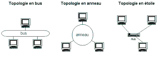
Fig. 1 — The three fundamental topologies: bus, ring, star
a) Bus topology
The stations are connected along a single cable (or segment); the theoretical limit is 255 stations, although this is only a theoretical figure as the speed would then be very low. Each connection to the cable is commonly referred to as a ‘node’.
Every message transmitted travels along the cable to reach the various stations. Each station checks the address specified in the message being transmitted to determine whether it is intended for that station. The cables used for this bus topology are coaxial cables. When a message is sent by a station, it is transmitted in both directions to all stations, which must then determine whether the message is intended for them.
The advantage of a bus system is that a fault at one station does not disrupt the rest of the network. It is also very easy to set up. However, if the bus connection is broken, the network becomes unusable. Furthermore, the signal is never regenerated, which limits the length of the cables.
⚠ Bus topology — obsolete
The bus topology using coaxial cable is now obsolete in local area networks. It was phased out in favour of the star topology using switches as early as the late 1990s.
b) Ring topology
The stations are connected in a continuous, closed cable loop. Signals travel along the loop in a single direction, passing through each of the stations. If desired, special privileges can be assigned to a workstation, which is then referred to as a privileged node.
Each station acts as a repeater to amplify the signal and send it to the next station. This topology allows for a throughput of nearly 90% of the bandwidth. This topology is fragile: if just one connection between two stations fails, the entire network goes down.
⚠ Ring topology — obsolete
Ring topology (Token Ring, FDDI) is now obsolete in corporate local area networks. It survives in an advanced form in resilient ring metropolitan area networks (SONET/SDH) and in certain industrial architectures.
c) Star topology (the most commonly used)
The stations are connected via cable segments to a central component known as a hub (hub) or switch (switch). The use of a hub followed by a switch offers certain advantages, particularly in the event of a link failure. The entire chain is not interrupted, as it would be in a simple bus topology. Via these devices, signals are transmitted from the sending computer to all computers on the network (in the case of a hub) or to the target computer only (in the case of a switch).
If a fault occurs in the central node, the entire network is brought to a standstill. Furthermore, adding a new station requires a new cable to be laid from the central node to the new station. This is currently the most widely used technology.
⚡ Star with a modern switch
With modern Layer 2 and Layer 3 switches, each port is dedicated to a full-duplex point-to-point connection, which completely eliminates collision domains and enables the interfaces to achieve their rated data rates. The hierarchical star topology forms the basis of all modern enterprise architectures.
d) The mesh network
A mesh network consists of several point-to-point links, with each node connected to all the others. The drawback is the number of links required, which can become very high depending on the number of devices.
This topology is found in large distribution networks (such as the Internet). Data travels across the network via various routes, either under the control of network supervisors or through distributed routing methods.
This also applies to extended Wi-Fi coverage. This is often referred to as a mesh topology, where Wi-Fi routers communicate with one another via a protocol such as OLSR (Optimised Link State Routing) to provide consistent coverage over large areas.
ℹ Other topologies
There are also tree networks, mesh networks and hypercube networks, which are less commonly used in standard LANs but are found in HPC (High-Performance Computing) clusters and supercomputers.
4. Modern LAN architectures
In today’s corporate networks, LANs are generally organised into several logical layers to balance performance, scalability and ease of administration. These are typically divided into the user access layer, the distribution layer and the core layer (core).
The access layer comprises the switches that directly connect client devices: PCs, printers, IP phones, Wi-Fi access points and connected devices. The ports on this layer are mostly 1 Gbit/s, with an upgrade to 2.5 and 5 Gbit/s to support Wi-Fi 6/6E access points and soon Wi-Fi 7. An increasing number of access ports provide power via PoE (Power over Ethernet) for Wi-Fi access points, IP cameras and Wi-Fi systems. Wi-Fi access points, IP cameras, IP telephones and various IoT devices, which greatly simplifies cabling.
In today’s corporate networks, LANs are generally organised into several logical layers to balance performance, scalability and ease of administration. These are typically divided into the user access layer, the distribution layer and the core layer (core).
The access layer comprises the switches that directly connect client devices: PCs, printers, IP phones, Wi-Fi access points and connected devices. The ports on this layer are mostly 1 Gbit/s, with an upgrade to 2.5 and 5 Gbit/s to support Wi-Fi 6/6E access points and soon Wi-Fi 7. An increasing number of access ports provide power via PoE (Power over Ethernet) for Wi-Fi access points, IP cameras and Wi-Fi devices. Wi-Fi access points, IP cameras, IP telephones and various IoT devices, which greatly simplifies cabling.
5. LAN technologies
Local area networks have seen enormous growth since the 1980s. A number of standards have successively dominated the market:
n Token Ring (IEEE 802.5): A network developed by IBM, based on the token ring protocol over a ring topology. Data rates of 4 and 16 Mbps. Now completely obsolete, having been replaced by Ethernet.
n Arcnet: Originally developed by Data Point, Arcnet is based on the token passing protocol (token passing). This technology supports bus and star topologies. Data rate: 2.5 Mbps. Obsolete.
n Ethernet (IEEE 802.3) — the most widely used: Developed by Digital, Xerox and Intel. Communication was long handled by the CSMA/CD protocol, but on modern networks (switch + full‑duplex) CSMA/CD is ’practically no longer used. Transmission takes the form of a frame (Frame) or block of information. Ethernet is now the universal LAN technology, available from 10 Mbps to 400 Gbps.
n Wi-Fi (IEEE 802.11): A wireless local area network operating on the 2.4 GHz, 5 GHz and 6 GHz frequencies, depending on the standard. It has become the standard for wireless connectivity in businesses and homes.
6. Access methods
In a local area network, each node is capable of transmitting over the same link cable. The set of rules governing access, usage time and monitoring constitutes the access protocol for the cables or communication media.
Layer 2 of the OSI reference model is divided into two sublayers:
n LLC (Logical Link Control) — Logical Link Control: ensures that the upper layers operate independently of the MAC layer.
n MAC (Media Access Control) — Media Access Control: is responsible for accessing the transmission medium to forward data frames. It attempts to prevent conflicts over access to the medium.
ℹ Couche LLC
The LLC layer ensures that the upper layers operate independently of the MAC layer. It is defined by the IEEE 802.2 standard and applies to all LAN technologies (Ethernet, Token Ring, Wi-Fi).